microspec
Practice without theory is blind, theory without practice is useless. Edison.
   Inicio      PIC microcontrollers

PIC microcontrollers projects

 
These microcontrollers of Microchip company, are currently the most popular, it may be because they have small economic versions, because they have reduced instruction set, because the availability of development tools and the facility to burn them.
 
If we are designing circuit composed of several integrated circuits of logical gates, timers, etc, we should consider that it is more convenient to use a microcontroller. The quantity of external components will be smaller, the printed circuit board simpler, and the circuit easier of to upgrade or to modify, so is worth while to learn how to use them.
 
Between the things we must do to learn about these microcontrollers:

1.  To read the technical data sheets of a small and economic microcontroller, to begin. It can be the PIC16F84A or the most recent PIC16F716.

2.  To get the compilation and simulation tools. MPLAB works well and is available for free in the Microchip's web page.
 
3.  To create programs for simple exercises and to check them with the simulator.

4.  To buy or to build a programmer. The “Pickit2” and “Pickit 3” programmers are official of Microchip and they are economic. They connect to the PC through USB port, through which it also feed.

 
If we want to build ourselves our programmer is convenient to choose some of the listing that works with "icprog", this program it works well and it is also free. We should also be sure to have some old computer with parallel or serial port as the programmer requires.
 
 
16F84 timer 0.


A way to be guide us with the configuration of the Timer 0 and other functions of the microcontrollers is to use the diagrams of equivalent blocks of the data sheets.

So in the figure, from left to right, we can see a square that corresponds to the pin RA4/TOCKI that is then the one to wich are applied the pulses in the case we want an external clock, next we see a ORex gate in which one of the inputs is TOSE(Timer 0 Source edge) that allows to choose the edge of the pulse which will increase the timer register, then we see a mutiplexor with 2 inputs, if T0CS (Timer 0 clock source) it is in 1 the branch that comes from the RA4 pin reaches the output, and if T0CS is in 0 the clock of the uC/4 reaches the exit.

The next multiplexer depends on the state of the PSA bit (Pre scaler assignment) and if it is in 0 it receives the pulses from the clock that we choose with TOCS and divides it according to the pre scaler that we choose with PS2, PS1 and PS0. And if PSA is configured with 1 we receive the pulses directly from TOCS. After going thru a synchronization block the pulses reach the TMR0 register increasing it.

When the TMR0 register overflows (it arrives to the maximum value and return to zero) the interruption flag of of the Timer 0 T0IF will be set, which will produce an interruption if the Timer 0 interruption is enabled in the INTCON register. 

To produce a certain time first we should consider that the uC increases the Timer register with a frequency equal to its oscillator divided by 4, or what is the same thing with a period of 4 times its clock, without considering the pre to scaler. (In the case of choosing to use the clock of the uC with T0CS). For example if the oscillator of the uC is  4MHz, then it will increase the TMR0 timer register with a frequency of 1MHz or each 1uS. Therefore the maximum time that we can obtain without pre scaler is 255uS. Because 255 is the maximum number of TMR0.

If we want a time, for example of 20uS then we should subtract 20 to the maximum value of TMR0, that is to say we should initialize TMR0 in 235.

The external clock is useful in case we need to use the TMR0 as counter of external events , for example when 10 pulses of a sensor are received, or also if we want to use a slower clock than the uC to obtain longer delays. 


Implementing ICSP of Microchip in our projects.

The serial programming protocols of the current microcontrollers, as the ICSP (In Circuit Serial Programming) of Microchip were conceived to program the microcontrollers in the application, that is to say, without removing the microcontroller of the board, with evident advantages mainly for massive production.

It is for this reason that the programmers like Pickit2 of Microchip don't bring a ZIF socket  (Zero Insertion Force).

When we develop prototypes we will need to prove the program of the microcontroller in protoboard. In this case we need to build a cable with a 6 pines female “Slim” connector   in one end and in the other tips for the protoboard. 

We can maintain the cable connected to the protoboard while we don't need it for another project.


ICSP connection cable to connect programmer with protoboard.


Programmer to protoboard connection. 

Anyway it will be more comfortable to build this cable once than remove many times the microcontroller of the protoboard to program it every time that is needed to correct the program.

Also:

  • it is usual that they are bridges or components crossed above the microcontroller. For example the typical 0,1uF capacitor in the supply pins.
  • the cable allows us in the future to use the in circuit debuging feature (In Circuit Debugger) that is available in the microcontrollers of high range and in the most recent in half range.
  • with the cable we can do without a external power supply and to use the 5V of the USB of the computer through the prgrammer to feed the circuit. The Pickit2 application has a check box to enable or to disable the power supply.

The programmer's connector has 6 pins. 5 are used to program microcontrollers and a sixth were left for possible auxiliary features:

  1. VPP   Programming voltage
  2. VDD  Positive power supply
  3. VSS  Negative ppwers supply
  4. PGD  Programming data
  5. PGC  Programming clock 
  6. AUX  Aux

Note.

Pin 1 marked with white arrow in Pickit2.

To succesfully program our microcontroller “in circuit” we should avoid that the components of our application, conected to the pins that intervene in the programming interfere with the programming signals.

For the pin VPP that is connected the MCLR of the microcontroller is enough with a “Power on reset” circuit and a 470 Ohm resistance to be isolated from this.

DO NOT CONNECT MCLR DIRECTLY TO +V
 
The signals PGD and PGC are connected RB7 and RB6 respectively and to be isolated FROM the application, resistances can be placed in series if the application allows it.

In last case if we don't want to get complicated and we have more than enough pins of IO we can leave RB6 and RB7 exclusive for ICSP.

 
Implementation of ICSP on protoboard.


Use of external interrupts of microcontrollers.

Many of the pulses that we want to read with the microcontroller appear in a brief and unexpected way. Although the current microcontrollers can run instructions in microsecond fractions, to evaluate the state of an entry permanently through a “loop” it doesn't guarantee the reading of the event. (ej keypads, ADC “Ready” signals, etc.)

To solve this problem, the microcontrollers have a mechanism called interruption, that in this case would be external, because there are also internal (timers, communication modules, etc).

The microcontrollers PIC of Microchip consists with an external interrupt associated to the pin RB0 and an interrupt “on change “(to the change) that is enabled when changing the state of the pines RB7, RB6, RB5 and RB4.

When taking place a change in an input pin associated to an interruption, internal hardware of microcontroller will activate a “flag”. If the interruption is enabled the program alters its normal flow and it jumps to an assigned address, called “Interruption vector” and starting from that address is written the code to execute when taking place the interruption: “Interrupt service routine” or RSI or ISR. Achieving this way to attend an event immediately.

To produce an interruption, the pin should be configured as input and the interruption should be enabled in the corresponding register.

To prove the operation of the interruption in the Microchip's  MPLAB simulator we can create a “Workbook” in “Debugger” / “Stimulus” / “New Workbook”. A window that allows us to apply different levels to the inputs pins will open.
 
To make click in a empty field of the column “Pin/Sfr” and an arrow will appear to deploy a menu, here we choose the pin that interests us to change and in the column “Action” we choose the action that will be applied to the pin. It can be “Toggle” that commutes the state of the pin.

To enable the elected stimulus we should make click in the “Fire”  box of the corresponding row.

If the interrupt this well configured, the flow of the programa should jump to the interruption vector when taking place an rising of falling edge, according to how the interruption was configured.

According to what is needed to make with the program, it is sometimes more convenient not to enable the interruption and to evaluate with a “loop” the state of the flag corresponding to the interruption. Contrary to the method that explained at the beginning, this way do ensure to receive the event, because although it is not immediately, although the event disappears, the interrupt stay activated.


Getting started with C for PIC microcontroller.

First we clarify that contrary to third companies, Microchip doesn't have C compiler for small microcontrollers, only for those of high range as the PIC18 family and superiors, which have been designed to work with language C. The C18 compiler can be downloaded in gratuitous way from Microchip homepage.

Although the Assembler language allows us to be solved any problem and first we should think of solving it with Assembler, because the microcontroller can be more economic, there are requirements that force us to program in a higher level language , as C:


  • To avoid complex algorithms of Assembler arithmetic.
  • Simplification of the code and decrease of the development time.
The cost of a 40 pins PIC18F4550 microcontroller is around $6.000(Chile).
 

TOOLS:

We should have installed MPLAB in the computer and the C18 compiler. Both can be downloaded in gratuitous way from the Microchip homepage.

First we should install MPLAB and later C18, which will be instaled in the root directory and it will configure MPLAB to integrate C18 in MPLAB. 

We will make a very simple example with the following tools:
  • MPLAB version 8.56
  • C18 version 3.36
  • Microchip HID bootloader aplicationv2.6a
  • PICDEM FS USB evaluation board with 18F4550 microcontroller.
  • USB A to B cable. That of printers serves.
 
For those who want to get one of my PICDEM FS USB compatible boards:


PIC18F4550 MICROCONTROLLER'S FEATURES:

  • 40 pins
  • 35 I/O pins.
  • USB 2.0 port
  • 4 timers
  • PWM output
  • 10 bit 13 channels ADC
  • Optimized architecture for C compiler.
  • 32K flash memory , 2048 SRAM, 256 EEPROM


PICDEM FS USB BOARD CHARACTERISTICS:

  • B type USBconnector
  • Incorporated push buttons and LED's in I/O pins. 
  • PIC18F4550 microcontroller.
  • Serial RS232 connector and interface .
  • Includes HID bootloader. (It is recognized by PC without driver necessity).
  • ICSP connector
  • Includes potentiometer in ADC input.


We should revise and to have a copy of these files on hand:

  • 39632e.pdf                               PIC18F4550 datasheets
  • c18_user_guide_51288j.pdf       C18 user's guide
  • p18f4550.inc                             register definintions
Located in C:Program filesMicrochipMPASM Suite
  • mplab_c18_getting_started_51295f.pdf
  • mplab-c18-libraries_51297f.pdf
  • hlppic18configset.chm

Located in C:MCC18doc

It is also advisable to have some book of ANSI C even for PC, to consult the syntax, structures of loops, etc.


CREATE PROJECT WITH MPLAB:


1. Create a folder with the name that we want to give to our project.
2. Copy in the folder the source file main.c available in link below.
3. Copy in the folder the linker file. Use: “rm18f4550 - hid bootload.lkr” to use with HID Bootloader.
4. In menu “Project” click in “Project Wizard” and in the following window click in button “Next”.
5. In this window choose “PIC18F4550” and click "Next".


6. In field “ActiveToolsuite” choose “Microchip C18 Toolsuite” and click "Next".


7. Now click “Browse” and open the folder previously created.   


8. Choose project name and click in “Save”.


9. In this window, “Step Three” click in “Next”.

10. Now in the window “Step Four” to locate the folder of our project and to select each one of the 2 files and to add them to the project making click in “Add”. Then click in “Next”.


11. In the window “Sumary” click “Finish” to create the project.


12. A schema of our project will appear like tree structure. To confirm that appear 
our 2 files: main.c in “Source files” and rm18f4550 - hid bootload.lkr in “Linker script.”  


If we revise with the file browser the folder of our project, we will see that now 3 more files were added. These files maintain the information about the project. The one that has extension “mcw” keeps the information of the open windows and their distribution on the work space. Later on we can open our project with this file or with that of extension “mcp.”

 
13. Now we are already under conditions of to compile and to execute our project with “Project” “Build All.”
 
If everything is OK we should obtain “Build Succeeded” in the window “Ouput.”
 
And if we revise at this time, with the file browser, the folder of our project will see that 3 more files were added. The one that interests us for the time being is the one that has extension “hex” because it is the one that will be loaded in the microcontroller.
 
To see in detail the execution of the program we should learn how to use the simulator of MPLAB. See section:
 
 
It is a very simple example of the “Getting started” guide to which was changed the output port to port D, because this incorporates 4 LEDs in the PICDEM FS USB board. 
The program configures the port D like output, reset it, and then leaves it permanently in high state. You can modify it later on to leave the LEDs permanently OFF.


Load program to the microcontroller.

One of the characteristics of the evaluation board is that comes with a bootloader already programed, this allows us to load the program to the microcontroller without a programmer's necessity, because the bootloader takes charge of receiving the “hex” file  through the USB port and to make that the microcontroller to program itself with the program of our application after the space that occupies the program of the “Bootloader.” 
 
The used bootloader is the denominated HID that is the one that Microchip uses in its last application libraries MAL(Microchip Aplication Library).

This bootloader is declared to the system like a human interface device (HID), which Windows recognize directly without driver necessity.

1. Execute “HID bootloader” application and will appear us this window:


The PICDEM FS USB evaluation board normally executes the program that has been loaded and if we maintain pressed one of its push buttons (S2) and reset it enters to the bootloader mode. When entering this mode it will be recognized by the system and by the Bootloader application, remember that it doesn't need driver, and the button will be enabled “Open Hex File” of the application in the PC.

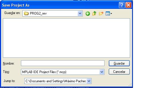
2.   Clicking in button “Open Hex File” we can load the file with extension “hex” that generate previously.

3.   Click in “Program/Verify” to load the microcontroller with our program. To confirm that the operation was carried out with success in the informative part of the main window.

4.   Press “Reset” push button of the board that makes it to leave the bootloader mode and execute our program. They should light the 4 LEDs that the board has connected in the Port D.

next we analyze the program so that you understands it and can use it as template and to modify it according to their necessities.

Analysis of the program.

1.   What is contained among / * and * / are comments and they appear in MPLAB of clear gray color:

/*Ejemplo 2 capítulo "Getting started" "Light LED"
modificado para puerto D que tiene LEDs en tarjeta USB_BOARD_4550  
XTAL =      20MHz
versión:     10 para bootloader HID
Modificado: 13 Agosto 2012
*/
 
2.   “//” it is used to add comments since from it appears until the end of the line:
 
#pragma config PLLDIV   = 5         // 20 MHz crystal/5 = 4MHZ para PLL 96MHz

Sometimes is used also to disable a line of the program without deleting it:

//#pragma config CP2      = OFF
 

3.   The commands “#pragma config” they indicate to the programer's program the value of the different bytes of configuration fuses that has the microcontroller:

#pragma config PLLDIV   = 5         // 20 MHz crystal/5 = 4MHZ para PLL 96MHz
 

4.   Since the bootloader program occupies a space permanently at the beginning of the program memory where are the reset vectors and interruption, we should re-address these vectors:

//      (PROGRAMMABLE_WITH_USB_HID_BOOTLOADER)

#define REMAPPED_RESET_VECTOR_ADDRESS                      0x1000

extern void _startup (void);        // See c018i.c in your C18 compiler dir

#pragma code REMAPPED_RESET_VECTOR = REMAPPED_RESET_VECTOR_ADDRESS

  void _reset (void)

  {

   _asm goto _startup _endasm

  }
 
5.   With “void main(void)” our main program begins. It is contained among key parenthesis "{}"
 
 
6.   “TRISD = 0;” it configures the port D like output
 

7.   The value that we assign to “PORTD” it will be reflected in the output:

PORTD = 0x0f;

With this the 4 less significant bits are activated, therefore the LEDs will ON.


Using MPLAB simulator.

1.   If we don't see the source code of our program at this time and we only see the tree scheme. Click in the file with extension. c to open it.

2.   If we select “Debugger/Select tool” we can see several debugging tools. “MPLAB SIM” it doesn't require additional hardware and it allows us to simulate on screen. Choose this option.

3.   A bar will be added with icons that allow us to execute the program step by step, all at once, skip functions, to leave these, etc.

Note:

F5, F6, F7, F8, F9 they correspond to the icons of the debugging bar.

 
4.   Having open our project to press “F5” (Halt) and then “F6” (Reset) to make sure that there is not an execution in progress.
 
Note:

It is necessary to make click in the white part of the window that contains the code to focus it and then to execute the debugging commands.

5.   Press “F7” to execute step by step.

We will go by several sentences of functions that C18 implements and that they appear in a separate window. We will concentrate on arriving to the function “main” of our program.
 
6.   In the first line after the main opening key can make double click to put a “Breakpoint”, what will allow us to execute until this point at once next time that we run the program from the beginning with F9.

7.   Press F5 and F6 for reset, then F9 and we will arrive to the “Breakpoint”. Then we can follow step by step.

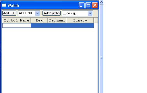
8.   To see how change the the microcontroller registers execute “View/Watch”:


Choose the register we want to observe in the combo box at left, for example for our program “Prog2”, choose “PORTD” and then click in the button “Add SFR”.

Let us execute step again to step observing how it changes the state of “PORTD”.

9.   When we close the project we should also save the “Work space”.
 
 
Programing E2PROM 93LC46 with Pickit2.
 

Although the serial E2PROM memorys doesn't communicate through ICSP like the microcontrollers, anyway the application of Pickit2 allows to program them. In the pickit 2 “readme.txt” file (located in C: FILES DE PROGRAMAMICROCHIPPICKIT 2 V2) we can see the connection between the programer's pins and those of the memory:

        PICkit 2 Pin             93LC Device Pin (DIP)

        (1) VPP                  1 CS

        (2) Vdd                  8 Vcc

        (3) GND                  5 Vss

        (4) PGD                  4 DO

        (5) PGC                  2 CLK

        (6) AUX                  3 DI

                                 7 PE - enabled (Vdd)

                                 6 'C' Device ORG

                                    Set to select word size

Note.

Pins 6 and 7 of E2PROM was not connected because in Datasheet it is seen that they are "NC".


Connection between Pickit2 and E2PROM 93LC46.
 

Also appear the connections to program E2PROM memorys of other families like those:

11LC…

24LC

25LC


  Volver